Solving a set of equations that represents a circuit is straightforward, if not always easy. However, developing that set of equations is not so easy. SCAM (Symbolic Circuit Analysis in MatLab)是一个适合初学者学习电路的求解工具 MATLAB fileExchange 有另一个人写了ObjectSCAM ,用起来会更加方便 我们将通过Simscape建模,以及SCAM求解来 理解这些基本电路;最后如过可能 转化成hspice输入检查结果
Solving a Cicuit Model
- loop-current (or mesh) method
- node voltage (or nodal) method
- Modified Nodal Analysis
Node Voltage Method1
- Selective a reference node (usually ground).
- Name the remaining n-1 nodes and label a current through each passive element and each current source.
- Apply Kirchoff’s current law to each node not connected to a voltage source.
- Solve the system of n-1-m unknown voltages.
Mesh Current Method1
We will define a “mesh” as an open “window” in the schematic drawing. Note that this method requires some modification to work with “non-planar” circuits (non-planar circuits are those that cannot be drawn without wires that cross each other without touching).
- Define each mesh and its corresponding current. This is easiest with a consistent method, e.g. all unknown currents are clockwise, all know currents follow direction on current source.
- Apply Kirchoff’s voltage law to each loop not containing a current source.
- Solve the system of n-m unknown voltages.
Comparsion of Node Voltage Method & Mesh Current Method
made on the basis of the circuit at hand. Depend on the number of non-current meshs and independent nodes.
modified nodal analysis (MNA) method - SCAM adapted2
- Selective a reference node (usually ground) and name the remaining n-1 nodes. Also label currents through each current source.
- Assign a name to the current through each voltage source. We will use the convention that the current flows from the positive node to the negative node of the source.
- Apply Kirchoff’s current law to each node. We will take currents out of the node to be positive.
- Write an equation for the voltage each voltage source.Solve the system of n-1 unknowns.
Summarize
MNA applied to a circuit with only passive elements (resistors) and independent current and voltage sources results in a matrix equation of the form:$\mathbf(Ax= z)$
For a circuit with n nodes and m independent voltage sources:
- The A matrix:
- is (n+m)×(n+m) in size, and consists only of known quantities.
- the n×n part of the matrix in the upper left:
- has only passive elements
- elements connected to ground appear only on the diagonal
- elements not connected to ground are both on the diagonal and off-diagonal terms.
- the rest of the A matrix (not included in the n×n upper left part) contains only 1, -1 and 0 (other values are possible if there are dependent current and voltage sources; I have not considered these cases. Consult Litovski if interested.)
- The x matrix:
- is an (n+m)×1 vector that holds the unknown quantities (node voltages and the currents through the independent voltage sources).
- the top n elements are the n node voltages.
- the bottom m elements represent the currents through the m independent voltage sources in the circuit.
- The z matrix:
- is an (n+m)×1 vector that holds only known quantities
- the top n elements are either zero or the sum and difference of independent current sources in the circuit.
- the bottom m elements represent the m independent voltage sources in the circuit. The circuit is solved by a simple matrix manipulation:$\mathbf{x = A^{-1}z}$
Algorithmic method for generating MNA (Modified Nodal Analysis) equations
see https://lpsa.swarthmore.edu/Systems/Electrical/mna/MNA3.html
Reactive Circuits and OpAmps3
Algorithmic method for generating modified nodal analysis (MNA) equations when the circuit has inductors, capacitors and/or operational amplifiers (op-amps).
Applying modified nodal analysis to circuits with inductors and capacitors presents no special difficulty if one uses the complex impedance of these elements.
$$ \begin{aligned} &Z_{R}=R \newline &Z_{L}=s L=j \omega L \newline &Z_{C}=\frac{1}{s C}=\frac{1}{j \omega C} \end{aligned} $$
MNA with Op Amps
Applying modified nodal analysis to circuits with ideal operational amplifiers (op- amps) is a bit more difficult.
The equation for the op-amp is not in terms of the voltage at its output, but rather it specifies that the two input terminals are at the same potential.
??
Treatment for Source!
Example
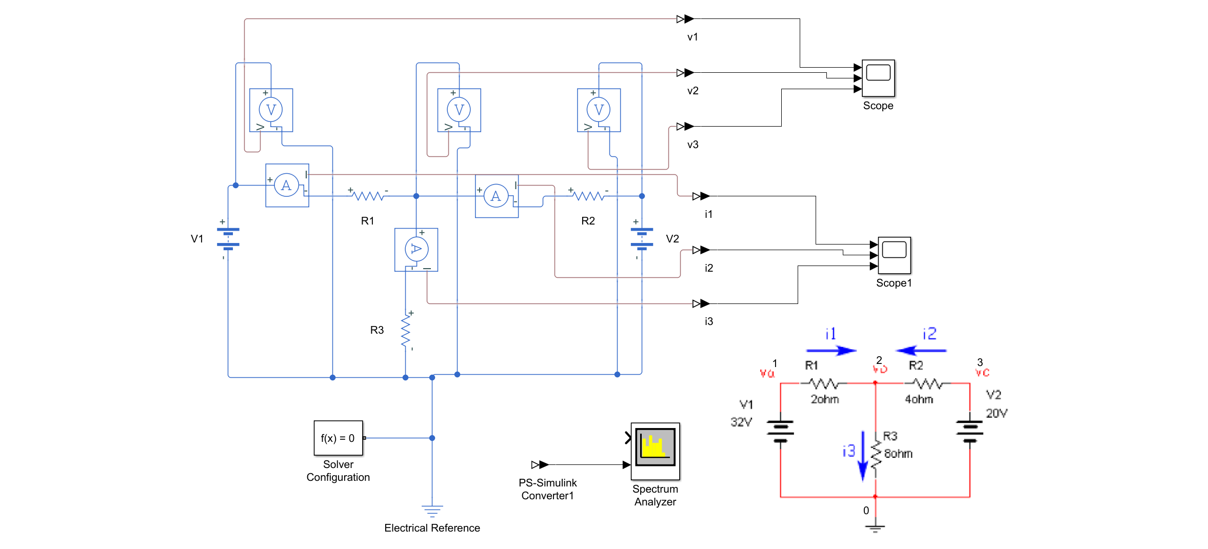
Example01

Netlist
 V1 1 0 32
 V2 3 0 20
 R1 1 2 2
 R2 2 3 4
 R3 2 0 8
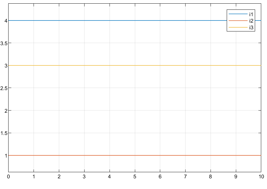
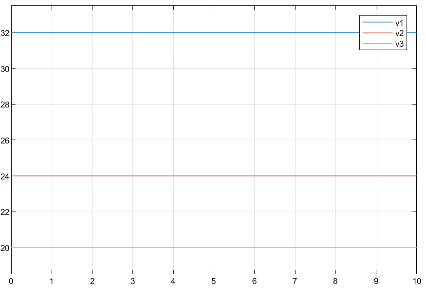
模拟结果
电流
 电压
电压

手解(Node Voltage Method)
Apply KCL $$ \begin{equation} \begin{aligned} i_{1}+i_{2} &=i_{3} \newline i_{1} &=\frac{v_{a}-v_{b}}{R_{1}}, \quad i_{2}=\frac{v_{c}-v_{b}}{R_{2}}, \quad i_{3}=\frac{v_{b}}{R_{3}} \newline v_{a} &=V_{1}, \quad v_{c}=V_{2} \end{aligned} \end{equation} $$
$$ \begin{equation} \begin{aligned} \frac{v_{a}-v_{b}}{R_{1}}+\frac{v_{c}-v_{b}}{R_{2}} &=\frac{v_{b}}{R_{3}} \newline \frac{V_{1}-v_{b}}{R_{1}}+\frac{V_{2}-v_{b}}{R_{2}} &=\frac{v_{b}}{R_{3}} \end{aligned} \end{equation} $$
we have $v_b = 24$
手解(Mesh Current Method)

Apply KVL
$$ \begin{aligned} &V_{1}-i_{1} R_{1}-\left(i_{1}-i_{2}\right) R_{3}=0 \newline &\left(i_{1}-i_{2}\right) R_{3}-i_{2} R_{2}-V_{2}=0 \end{aligned} $$
$$ \begin{array}{r} \left(R_{1}+R_{3}\right) i_{1}-R_{3} i_{2}=V_{1} \newline -R_{3} i_{1}+\left(R_{2}+R_{3}\right) i_{2}=V_{2} \end{array} $$
$$ \left[\begin{array}{cc} \left(R_{1}+R_{3}\right) & -R_{3} \newline -R_{3} & \left(R_{2}+R_{3}\right) \end{array}\right]\left[\begin{array}{l} i_{1} \newline i_{2} \end{array}\right]=\left[\begin{array}{l} V_{1} \newline V_{2} \end{array}\right] $$ we have $i_1 = 4,i_2 =1$
手解(MNA)- adapted in SCAM
- Apply step 2 (currents through the voltage sources with current from positive node to negative node)

- Apply step 3 (with positive currents out of the node):
- Node 1: $i_{v 1}+\frac{v_{1}-v_{2}}{R_{1}}=0$
- Node 2: $\frac{v_{2}-v_{a}}{R_{1}}+\frac{v_{b}}{R_{3}}+\frac{v_{2}-v_{3}}{R_{2}}=0$
- Node 3: $i_{v 2}+\frac{v_{1}-v_{2}}{R_{2}}=0$
- Apply step 4:
- $v_1 = V_1$
- $v_3 = V_2$
- Apply step 5: $$ \left[\begin{array}{ccccc} \frac{1}{R_{1}} & -\frac{1}{R_{1}} & 0 & 1 & 0 \newline -\frac{1}{R_{1}} & \frac{1}{R_{1}}+\frac{1}{R_{2}}+\frac{1}{R_{3}} & -\frac{1}{R_{2}} & 0 & 0 \newline 0 & -\frac{1}{R_{2}} & \frac{1}{R_{2}} & 0 & 1 \newline 1 & 0 & 0 & 0 & 0 \newline 0 & 0 & 1 & 0 & 0 \end{array}\right]\left[\begin{array}{c} v_{a} \newline v_{b} \newline v_{c} \newline i_{v 1} \newline i_{v 2} \end{array}\right]=\left[\begin{array}{c} 0 \newline 0 \newline 0 \newline V 1 \newline V 2 \end{array}\right] $$
Solved by SCAM
I fixed a little bug when applying this class under the version MATALB R2022a.
1Cir_01 = ObjectSCAM;
2Cir_01 = Cir_01.create('example1.cir');
3Cir_01
Cir_01 =
ObjectSCAM - 属性:
netlist: {5×4 cell}
     R3: 8
     V1: 32
     R2: 4
   I_V2: -(R1*V2 - R3*V1 + R3*V2)/(R1*R2 + R1*R3 + R2*R3)
    v_2: (R3*(R1*V2 + R2*V1))/(R1*R2 + R1*R3 + R2*R3)
    v_3: V2
   I_V1: -(R2*V1 + R3*V1 - R3*V2)/(R1*R2 + R1*R3 + R2*R3)
    v_1: V1
     V2: 20
     R1: 2
我们可以求解对象
1Cir_01.resolveVar('v_2')
ans =
 2
1Cir_01.resolveEq('(v_1-v_2)/R1')
2Cir_01.resolveVar('(v_1-v_2)/R1')
ans =

V1/2 - (R3*(R1*V2 + R2*V1))/(2*(R1*R2 + R1*R3 + R2*R3))

ans =

4
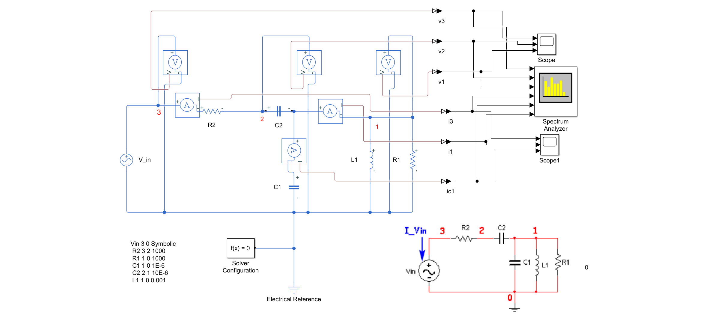
Example02 RLC

Example03 RCL with Op
Simulation in Hspice
G. Rizzoni and J. Kearns, Principles and Applications of Electrical Engineering (2022). ↩︎ ↩︎
Linear Circuit Analysis: Time Domain, Phasor and Laplace Transform Approaches, Oxford University Press , 2001. ↩︎
Litovski, V, Zwolinski, M, VLSI(Very large-scale integration) Circuit Simulation and Optimization, Kluwer Academic Publishers, 1997. Modified Nodal Analysis and Computer Simulation. ↩︎

